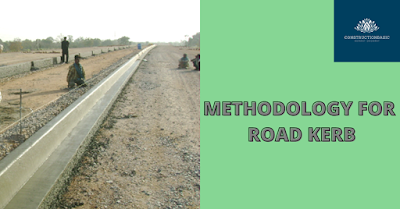
METHODOLOGY FOR ROAD KERB
This article covers constructing cement concrete kerbs and kerbs with channel with the
lines, levels and dimensions as per approved drawings.
The work involves construction of in Situ- Cement Concrete Kerb & Kerb with channel along medians, junctions, edges, service Road, separators etc. to the line, level and dimensions as shown in the contract drawings.
Materials
Kerbs
and kerb with channel will be provided in cement concrete of grade M20 in
accordance with Section 1700 of M.O.S.T. Specifications.
Construction Methodology
This work will be done as per technical specification clause 408.
The total quantity of kerbs and kerb channels as per the Bill of Quantities in Running meter.
The above quantity is for the entire stretch and planned for execution as per the construction program.
Cement Concrete will be transported through transit mixer of 6m³ capacity.
SUMMARY OF PROPOSED EQUIPMENT:
a. Kerb machine with extruder.
b. b. Concrete Truck/Transit mixer.
c. c. Joint cutter.
Manpower
Skilled Manpower to drive that machinery is as follows
(With each crew):
Engineer - 1
No. .
Surveyor - 1
No.
Mason - 1
No.
Transit Mixer Opt - 2
Nos.
Kerb Machine Opt - 1
Nos
Helper - 1 nos.
W/Tanker Driver - 1
Nos.
Labour - 4
Nos.
Construction
Operation
The surface level of WMM on which the road kerb is to be laid is to be made up with the leveling course in order to lay the kerb.
The level will be maintained and checked in reference to the finishing level of the roadwork with auto Level through sensor system of machine. The road kerb machine will travel on the WMM surface.
The mixed concrete M-20 with very low slump (at the time of pouring in the hopper of machine) carried in transit mixers from the batching plant and will be poured into the hopper of the road kerb machine. The slump at the batching plant to be kept between 25 to 30mm and slump will be increase or decrease with the help of increasing or decreasing the dose of super plasticizer as per the requirement. The most important point is that the slump should be zero at the point of pouring concrete in to the hopper of road kerb machine.
There shall be no honeycombing or irregularity in the surface area. If during casting kerb, it is found necessary to repair / touch up, a mason with helper will move along the machine and repair.
After the concrete is finally set, the kerb will be cut at a interval of 5m or as per requirement of ground conditions with concrete cutting machine.
The
portion near to culverts and bridges where the kerb cannot be laid with
machine, the same will be laid with precast units as per MOST specification.
Freshly
cast kerb will be covered with hessian cloth / gunny bags and kept moist with
water for 7 days as the concrete will achieve a good strength, since slump of
the concrete at the time of kerb casting is almost zero.
Alternatively,
approved curing compound may be applied on the kerb immediately after casting
if decided by the Engineer.
Location : Date :
Layer : Inspection No. :
|
S.No.
|
Description |
YES |
NO |
NA |
|
1 |
Previous
layer is approved |
|
|
|
|
2 |
Mix
and its materials are approved |
|
|
|
|
3 |
Concrete
conveying arrangement (including transit mixers) available in working
conditions and of sufficient capacity |
|
|
|
|
4 |
Alignment
|
|
|
|
|
5 |
Level |
|
|
|
|
6 |
Dimension |
|
|
|
|
7 |
Class
of finish |
|
|
|
|
8 |
Curing
arrangements |
|
|
|
|
9 |
Saw
cut provided for expansion joints |
|
|
|


0 Comments
Please do not enter any spam link in the comment box.